NodeMCU and AWS IoT: A cost-effective, DIY solution for sending data to the Cloud using the Arduino IDE
NodeMCU and AWS IoT: A cost-effective, DIY solution for sending data to the Cloud using the Arduino IDE
By Shrey Thapar
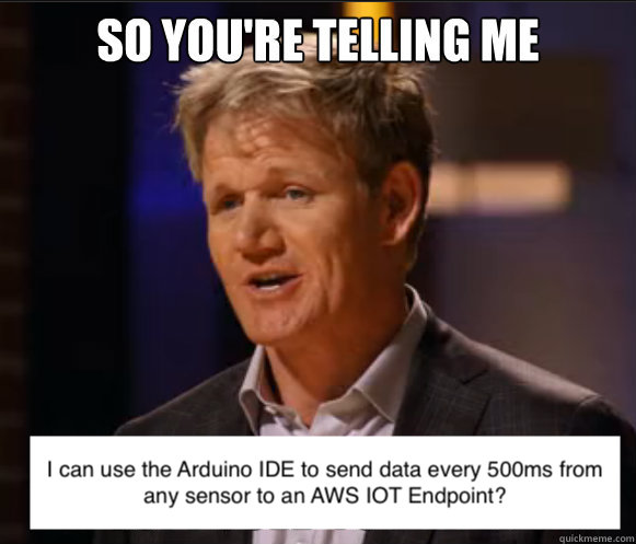
So…
Let’s say you’ve purchased, or want to purchase a sensor to monitor something of interest. It could be the humidity of the soil, CO2 levels in the air or the ambient sound in the room.
You then want to be able to send this data to the cloud. Not just any cloud though, but you want to send this data to AWS. Send it to AWS to utilize the plethora of services it offers to ingest, analyze, stream and showcase that data? If so, you’ve come to the right place!
The sensor I was given to work with was the CCS811 Environmental Sensor that can closely monitor CO2 and total volatile organic compounds (TVOC) levels in the air. Measured in parts per million (ppm) and parts per billion (ppb), these are the following thresholds for CO2 and TVOC levels.


The first step is to connect this sensor to a board. There are a number of electronic boards out there that allow for the rapid development of IoT projects. Some boards, however, can be quite costly and have a steep learning curve. One board that bypasses these hurdles is the ESP8266 NodeMCU board. Not only is it a cost-effective microcontroller with an integrated WiFi chip, but it supports development in the Arduino IDE. This makes it extremely easy to write code, install libraries for almost any sensor imaginable, and upload it to the board.
Armed with this knowledge, what do I want to be able to do with this board? Essentially, I want to be able to send environmental sensor data in a JSON format to AWS’ IoT Core which is a service that lets you connect and route trillions of messages from your IoT devices to AWS services at a low latency and high throughput. Here is an architecture diagram showcasing this:

And the sensor reading would be displayed like this in the AWS IoT MQTT Client:
{
  "sensorID": "123456",
  "measurementType":"CO2",
  "measurement":"345",
  "timestamp":"2022-04-27 23:11:37.000Z"
}

{
  "sensorID": "123456",
  "measurementType":"TVOC",
  "measurement":"420",
  "timestamp":"2022-04-27 23:11:37.000Z"
}
When done correctly, this board can be a very useful tool to utilize and send data to an endpoint in AWS’ IoT Core; however, lack of documentation online as well as strict security rules from AWS makes it easy to run into a number of potential authentication, and connectivity issues. The purpose of this article is to go over the potential hurdles I ran into when trying to execute this idea and how I got around those hurdles.
Development Process
The idea is simple. Use your normal run of the mill breadboard, jumper wires and Arduino compatible sensor of choice (I’m using a Keyestudio CCS811 Air Quality Sensor) and hook it up to your ESP chip like this.

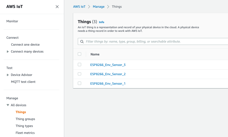
Once that’s done, you register and provision your “Thing” in the AWS IoT Core Console. This is where we run into our first hurdle.
Hurdle #1: How do I register my NodeMCU with AWS?
As we can see in this AWS article on provisioning, there are a number of different ways to provision the device. To authenticate client and device connections we need a X.509 client certificate for each device. As seen on this article on X.509 certificates, there are three types of X.509 certificates AWS supports. The ones generated by AWS IoT themselves, the ones signed by a CA registered with AWS IoT, or a CA not registered with AWS IoT.
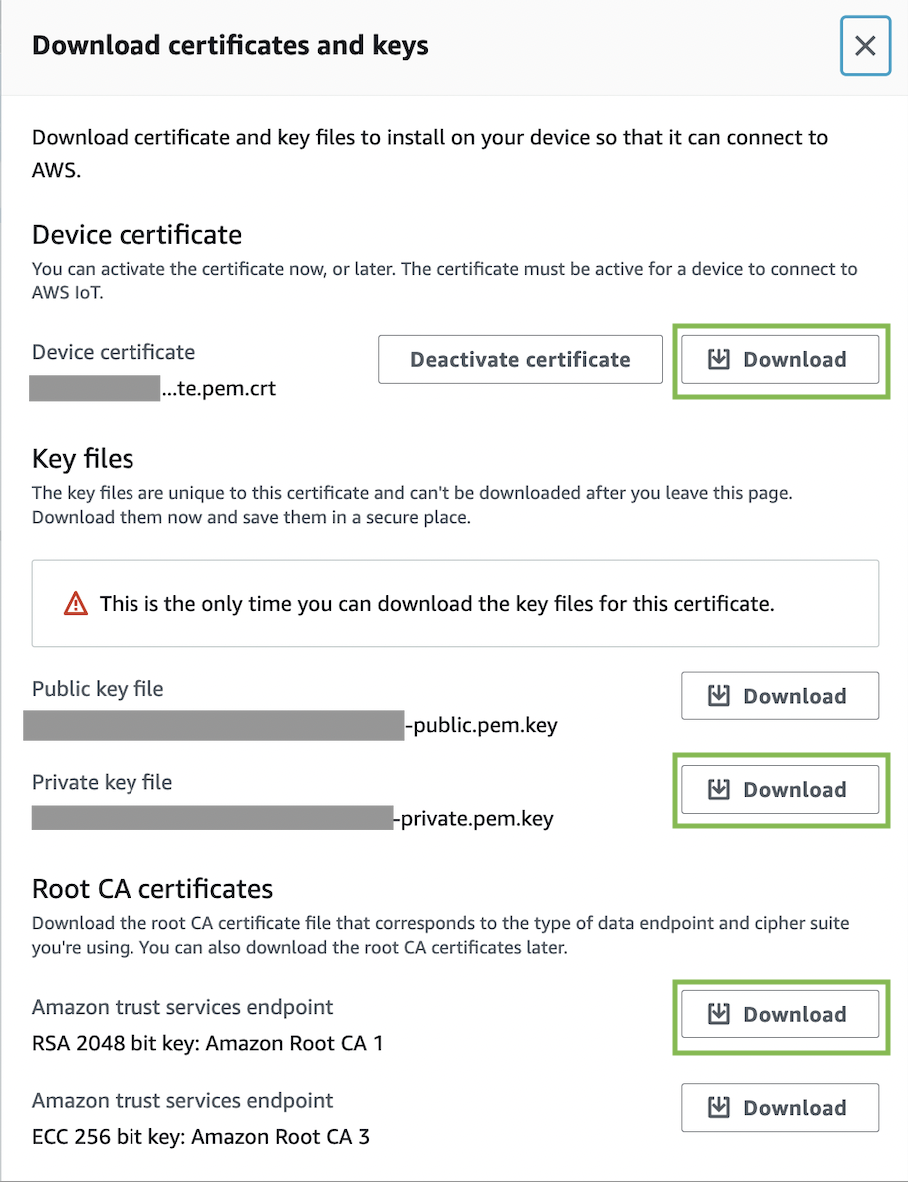
I decided to go with Just in Time Provisioning (JITP) so that I could manually install the X.509 certificates generated by AWS IoT on each device. These certificates are generated once we register a “Thing”in the IoT console and are prompted to download the following:
Once the certificates are burned onto the device, we can authenticate with AWS without any issues and shift our focus to development and coding instead.
Great! Now that we have decided on the provisioning method, we can go ahead and register the device in the console and have something like this:
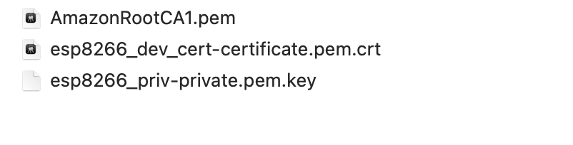
Once that is done, we can download the Device Certificate, Private Key and RootCA1 to upload to the board’s file system. Here is where we run into our second hurdle.
Hurdle #2: How do I upload the certificates to the board’s memory?
Everytime we upload a sketch to the NodeMCU board (through the Arduino IDE), it overwrites the previous content that was on the system’s flash memory that stores the sketches. We want these certificates to permanently reside on the board’s non volatile filesystem and not get overwritten. The way I did this was to utilize the Arduino ESP8266 File System Plugin.
Once installed, something like this will appear in the Arduino IDE.
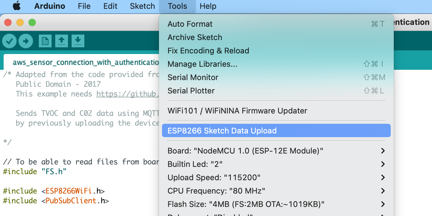
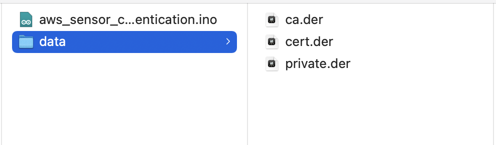
Then, by creating a ‘data’ directory in the sketch folder, we can place our certificates in there, select ‘Sketch Data Upload’ and the files should be uploaded to the NodeMCU’s file system.
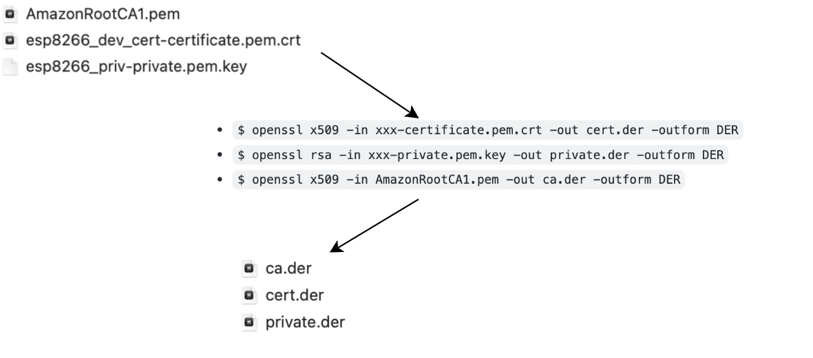
Wait a second! Are these the same files we downloaded from AWS? The file names and types for those were of type “pem” but these are of type “der”. Yes, these are the same files. I had to convert them and the reason why, is what brings us to our third hurdle.
Hurdle #3: How do I convert the certificates to a format the board understands?
We can’t simply place these files into the ‘data’ directory of the sketch because they are encoded in the “.PEM” format which is a base64 encoding, something the NodeMCU does not understand. Thus we have to go ahead and install OpenSSL as seen in this article and convert the files to the “.DER” format. This is a binary encoding for certificates that the NodeMCU board does understand.
Okay, so we have now
- Built the device
- Provisioned it with AWS
- Uploaded the certificates to the board
We are almost there! By doing these steps we have ensured that we will not have any authentication issues, but what about connectivity issues. How do we connect it to the WiFi without having to hardcode the credentials and what if we are in an enterprise environment where WiFi can’t be configured as easily?
Hurdle #4: How do I prevent the hardcoding the WiFi credentials?
Although we could hardcode the wifi credentials inline with the code, this poses a security risk and if the device is moved to another location, we would have to retype and reupload the sketch with the appropriate credentials. This is not feasible. A simpler solution is to use a WiFi Manager Library. By installing this library, we create a WiFi access point that can be accessed by any WiFi enabled device. Simply open the portal, choose the WiFi that you want to connect to, enter the credentials and you are good to go.
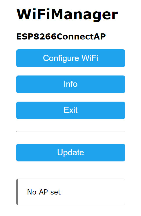
To see how to handle and setup the WiFi library functions in the sketch please refer to Code Snippet #2
Hurdle #5: How do I register my device on enterprise WiFi?
One of the main reasons I had connectivity issues was because I was trying to directly connect my IoT device to a WiFi Protected Access (WPA) Enterprise connection without a router. This can be a difficult task as IoT devices mostly don’t support WPA Enterprise connections and consequently, enterprises have a number of security protocols in place to prevent any internet enabled device from just connecting.
Thus, in order to connect to the WiFi you have to pre-register the MAC Address of the device through a portal or by contacting your administrator.
Please refer to Code Snippet #3 to see a sketch to grab an ESP8266’s MAC Address and chip id (a useful identifier metric when sending data to AWS)
Hurdle #6: How do I send the sensor data appropriately to AWS?
Less of a hurdle and more of figuring out a way to send the data in a JSON format along with an ISO timestamp. This is so that other AWS services like Lambda can parse and analyze the payloads further. For this I used the NTP Client library and the Arduino JSON library.
To see how to utilize the NTP and JSON Library publish custom JSON messages to MQTT please see Code Snippet #4 and #5
Conclusion
After successfully resolving these issues, I was able to send data from a Keyestudio CO2/TVOC Air Quality Sensor to the cloud. There are an innumerable number of options of what can be done with the data once it is sent to a specific AWS IoT topic. On my end, this data was then parsed and handled by a Lambda and streamed through AWS Kinesis Data Firehose and loaded into Timestream. It could have also been loaded into DynamoDB. The possibilities are endless.
Using this board, it is possible that any organization (enterprises, universities, etc) could utilize and provision these devices at a larger scale in the future. This is because the NodeMCU has the potential to be part of a highly customizable solution that can send high granularity data to the cloud. This eliminates the need to purchase third party sensor solutions as well as third party API request costs making it extremely cost effective for prototyping and testing.
Reflection
Although I had a decent amount of hands-on experience with Arduino, prior to this project, I did not know much about how devices securely communicate over the internet. After setting up this IoT sensor, I learnt about the MQTT Protocol, how devices use the publish / subscribe design pattern, different types of provisioning techniques and gained a better understanding of C++ and AWS services.
If you want to see a comprehensive step by step guide of how to do this please follow the guide posted on this Github Repository.
Future Improvements
Despite overcoming a number of hurdles during the development process, there were some aspects during provisioning that I came across that I still plan to work on in order to improve the project. The following are some of the aspects that I could improve on:
- Eliminate the need to hardcode an AWS endpoint and IoT Topic inline with the code
- Although I was able to figure out how to remove hardcoding the WiFi credentials, the aforementioned values still need to be hardcoded. Need to find a library or develop a custom web server that can allow tweaking of specific variables without needing to open and change the sketch
- Be able to provision the IoT Device through CloudFormation or the Cloud Development Kit (CDK).
- Right now, I have to manually register the device through the AWS console and download the certificates. Want to potentially come up with a way to do it utilizing AWS’ Infrastructure as Code services such that they can be deployed automatically in the cloud when the software is run.
Code Snippets
Code Snippet #1: Reading and loading the certificates from the board’s memory
(Adapted from the code in this repository)
// To be able to read files from board's non volatile file system
#include "FS.h"
This is included in the ‘setup’ part of the sketch. Purpose of this code is to load and read the certificate files ensuring successful authentication to AWS.
if (!SPIFFS.begin())
  {
    Serial.println("Failed to mount file system");
    return;
  }

  Serial.print("Heap: ");
  Serial.println(ESP.getFreeHeap());

  // Load certificate file
  File cert = SPIFFS.open("/cert.der", "r"); // replace cert.crt with your uploaded file name
  if (!cert)
  {
    Serial.println("Failed to open cert file");
  }
  else
    Serial.println("Success to open cert file");

  delay(1000);

  if (espClient.loadCertificate(cert))
    Serial.println("cert loaded");
  else
    Serial.println("cert not loaded");

  // Load private key file
  File private_key = SPIFFS.open("/private.der", "r"); // replace private.der with your uploaded file name
  if (!private_key)
  {
    Serial.println("Failed to open private cert file");
  }
  else
    Serial.println("Success to open private cert file");

  delay(1000);

  if (espClient.loadPrivateKey(private_key))
    Serial.println("private key loaded");
  else
    Serial.println("private key not loaded");
  // Load CA file
  File ca = SPIFFS.open("/ca.der", "r"); // replace ca with your uploaded file name

  if (!ca)
  {
    Serial.println("Failed to open ca ");
  }
  else
    Serial.println("Success to open ca");

  delay(1000);

  if (espClient.loadCACert(ca))
    Serial.println("ca loaded");
  else
    Serial.println("ca failed");

  Serial.print("Heap: ");
  Serial.println(ESP.getFreeHeap());
}
Code Snippet #2: Setup and Configure the WiFiManager Library
Setup WiFi function that is called in the ‘setup’ loop. Can create a custom password for the access point as well as add a custom parameter to the portal.
void setup_wifi()
{

  WiFiManager wifiManager;

  // if uncommented, will reset stored wifi credentials on every boot
  // wifiManager.resetSettings();

  wifiManager.autoConnect("ESP8266ConnectAP", "password");
  WiFiManagerParameter custom_text_endpoint("key_num", "Enter your endpoint here", "", 60);
  delay(10);
  // We start by connecting to a WiFi network
  espClient.setBufferSizes(512, 512);
  Serial.println();
  while (WiFi.status() != WL_CONNECTED)
  {
    delay(500);
    Serial.print(".");
  }

  Serial.println("");
  Serial.println("WiFi connected");
  Serial.println("IP address: ");
  Serial.println(WiFi.localIP());

  timeClient.begin();
  while (!timeClient.update())
  {
    timeClient.forceUpdate();
  }

  espClient.setX509Time(timeClient.getEpochTime());
}
Code Snippet #3: How to view the board’s Chip ID and MAC Address
A completely separate sketch, not part of the sensor connection sketch. Run this simple script on your board and open the Serial Monitor to view the MAC Address and Chip ID details.
#include <ESP8266WiFi.h>
void setup() {

  Serial.begin(9600);
  Serial.println();

}

void loop() {
  Serial.println("The ESP8266 Chip ID is: ");
  Serial.println(ESP.getChipId());
  delay(2500);
  Serial.println("The ESP8266 Chip MAC Address is: ");
  Serial.println(WiFi.macAddress());
  delay(2500);

}
Code Snippet #4: Creating a JSON Object with sensor and time data to publish to the Cloud
Called in the loop part of the sketch, this publish message function sends CO2 readings and TVOC readings to AWS. (Note this can be customized for any type of sensor readings).
void publishMessage()
{
  StaticJsonDocument<200> docCO2;
  StaticJsonDocument<200> docTVOC;
  char jsonBuffer[512];

  docCO2["sensorId"] = String(ESP.getChipId());
  docCO2["measurementType"] = "CO2";
  docCO2["measurement"] = String(co2);
  docCO2["timestamp"] = nowbuf;

  serializeJson(docCO2, jsonBuffer); // print to client
  client.publish(aws_topic, jsonBuffer);

  docTVOC["sensorId"] = String(ESP.getChipId());
  docTVOC["measurementType"] = "TVOC";
  docTVOC["measurement"] = String(tvoc);
  docTVOC["timestamp"] = nowbuf;

  serializeJson(docTVOC, jsonBuffer); // print to client
  client.publish(aws_topic, jsonBuffer);
}
Here the in the function we
- Create 2 JSON objects, 512 characters each.
- The readings come out in a specific JSON format.
- The chipID comes directly from the ESP board
- The co2 and tvoc values are global variables loaded directly from the sensor.
- The ISO format timestamp is loaded from the NTP client
- Both objects are serialized and published to the AWS topic
Code Snippet #5: How we got the ‘nowbuf’ value from the NTP Client.
void setClock()
{
  configTime(3 * 3600, 0, "pool.ntp.org", "time.nist.gov");

  Serial.print("Waiting for NTP time sync: ");
  time_t now = time(nullptr);
  while (now < 8 * 3600 * 2)
  {
    delay(500);
    Serial.print(".");
    now = time(nullptr);
  }
  Serial.println("");
  struct tm timeinfo;
  gmtime_r(&now, &timeinfo);
  Serial.print("Current time: ");
  Serial.print(asctime(&timeinfo));  // Converts the timestamp to the ISO date and time format  Serial.print(strftime(nowbuf, sizeof(nowbuf), "%Y-%m-%d %T", gmtime_r(&now, &timeinfo)));  // appends a ‘.000Z’ to the end and the nowbuf value is now updated to be published
  strcat(nowbuf, ".000Z");
}